PKDIMA
PKDIMA is an “Angular Dimension” entity which quickly snaps to the angular features of your part and dynamically helps the user position the dimension text. This allows CAD user’s more control in laying out angular dimensions with an intuitive command interface which draws quicker and yields neater looking drawings.
The typical method for dimensioning with PKDIMA is to use an Endpoint modifier to select the point from which the leader extension will begin (point 1). The second prompt reads “Pick point/entity for leader 2,” using the Endpoint modifier, click the second entity that makes up the angular dimension (shown as point 2). The entire dimension will dynamically appear as the cursor is moved to the third click which positions the angular arc (point 3) rubber banding the extension lines. This provides the CAD user with a visual capability to position the dimension. The fourth click can be bypassed with a right mouse click to position the text at point 3, or a forth point can be used to drag the text position to any desirable location.
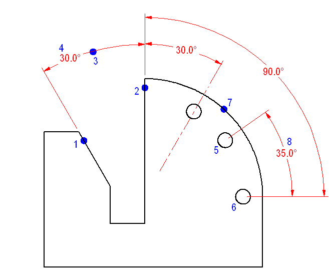

PKDIMA can also be used to dimension more complex entities that might not fix to entities that intersect at an obvious vertex. As shown in the second example, by using a Center Point modifier at point 5 and 6, PKDIMA will pop-up a message box (Figure 2) informing the user that an additional point is required. After canceling the warning box, a rubber band cursor will dynamically extend towards the vertex. In the example shown, point 7 uses the Center Point modifier to pick the actual vertex found at the center of the part radius. Many different entries could have been used, such as typing an XY point at the command line, or just typing an angle. For example, if the pop-up occurred after point 6 was chosen, then typing 180 (for the degrees toward the vertex) would satisfy the command’s mathematical requirement for determining the vertex. What is left is to dynamically position the dimension text (point 8).
What is the best way to use PKDIMA?
To call this command, you can type PKDIMA at the command line. However, the most productive way to use PK Data commands is to integrate them into the Menu and Icon Bar, so that they can be called efficiently when you are drawing.
Adding to your Menu
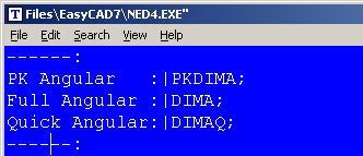
Before editing your menu, it is recommended that you backup the menu file. It can be found in the root directory of FastCAD or EasyCAD and is called FCW7.MNU or ECW7.MNU respectively. The backup file can come in handy if things do not work well after editing, you can always return to the original factory menu. In the CAD program’s root directory, you can find and launch NED4.EXE. FastCAD provides this as a text editor for making such customized changes. Use File > Open... to begin editing FCW7.MNU or ECW7.MNU. Scroll down to the Dimension menu area and change the commands in the Angular Dimension section, to read as follows:
Adding to your Icon Bars
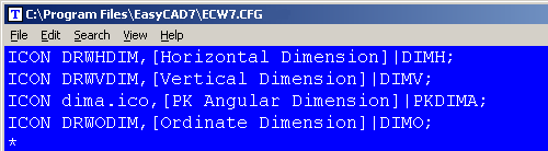
Before editing your Icon bar configuration, it is recommended that you backup the configuration file. It can be found in the root directory of FastCAD or EasyCAD and is called FCW7.CFG or ECW7.CFG respectively. The backup file can come in handy if things do not work well after editing, you can always return to the original factory configuration. In the CAD program’s root directory, you can find and launch NED4.EXE. FastCAD provides this as a text editor for making such customized changes. Use File > Open... to begin editing FCW7.CFG or ECW7.CFG. FastCAD and EasyCAD do not have an icon for any of the Angular Dimension commands. The following example shows an approach for adding such an icon, however it will require drawing artwork to represent the icon and naming the file: dima.ico. The example below codes PKDIMA as a Left-Click icon pick.
Download zip file with PK Free Icon artwork. Extract directly into FastCAD or EasyCAD v7 program root directory.
For additional information, consult the FastCAD Help files to learn how to add custom icon artwork and the command code to your configuration. If you need support, consult the Evolution Computing community’s bulletin board at the link below. The community is always open to helping users who are learning to customize the look and feel of their CAD software.